PING! – Augmented Pixel
Augmented Reality Videogame
In the decade where videogames were born, everything virtual looked like rectangular blocks. From today’s perspective, the representation of a tennis court in the earliest videogames is hard to distinguish from a digital soccer or a basketball field of that time.
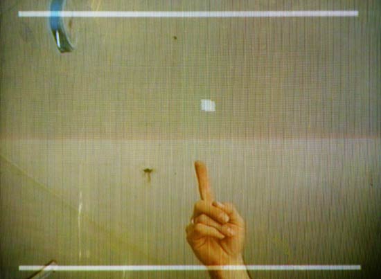
“PING! – Augmented Pixel” is a seventies style videogame, that adds a layer of digital information and oldschool aesthetics to a video signal: A classic rectangular video game ball moves across a video image. Whenever the ball hits something dark, it bounces off. The game itself has no rules and no goal. Like GTA, it provides a free environment in which anything is possible. And like Sony’s Eyetoy, it uses a video camera as game controller.
What I found interesting when I developed this game, is that it could have been made already in the seventies. The technology that I used for it is (in a way) similar to what Atari used for the first Pong. It becomes even more awkward, if you think that the electronic components for capturing and evaluating a video signal are cheaper than the rotary game controllers that Atari used. But still, from an economic point of view it makes sense that Eyetoys weren’t the ultimate controllers during the 70s, as a video camera was hard to afford back in the days.
How it works
The game is programed with AVR-GCC on an ATmega8 microcontroller that runs with 16MHz. The controller gets basic videosignal synchronisation information from an LM1881 sync separator that triggers two hardware interrupts. One for drawing a new image, the other one for drawing each single line. The controller evaluates the brightness around the pixel (/ball) via its comparator input. Drawing the white image overlay is realized with a simple pull-up resistor in the signal line.
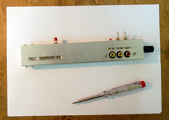
I've opened the console to show you its contents:
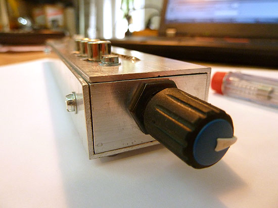
There’s a 9V battery, a little circuit board and all the switches.
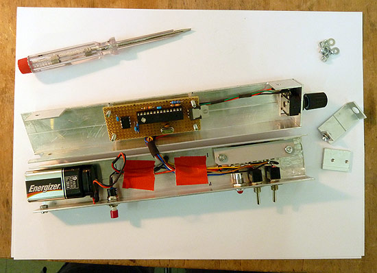
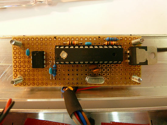
Let's have a closer look on the circuit board:
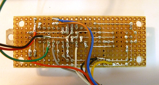
And here's the board seen from the bottom:
Making your own PING!
I don't provide a complete step-by-step instruction of how to make one. But I can give you some hints in case you want to make your own PING!
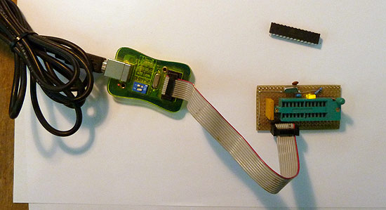
First, you have to program the firmware onto the microcontroller. I use this cheap ISP programmer that I bought here. [Updated information: Those days you can also use an Arduino board as an ISP programmer - simply google for “Arduino as ISP”]
(ISP stands for In System Programming)
If you just get started and want to know in detail how to program an AVR – here’s a great tutorial. Sorry folks, this link is German only. But Google will also find you a good English source.
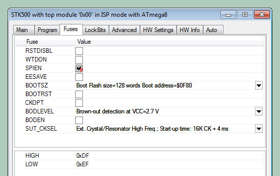
The Fusebit settings for the controller are clear: Just tell the controller to use the external crystal as clock. (SUT_CKSEL)
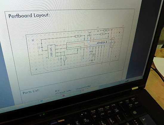
Next step is to build the electronics. You can find a link to the schematics at the end of this page.
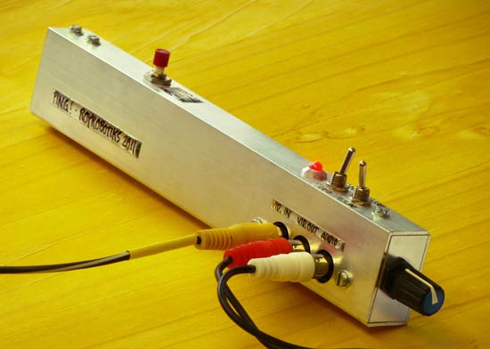
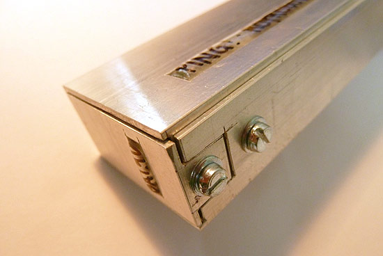
Finally, you have to make a case. There are many options - I used a U-shaped extruded aluminum profile. The different metal parts are all built out of the same profile.
Here's a detail:
That’s it so far about the hardware. Concerning the firmware: Be aware, that the program is for PAL video systems only. If you want to play this game on your NTSC system, you have to adapt the timing in the source code.
As all those hints were a bit vague, I'll also copy a comment which I left on a Hackaday article about the project.
There, I'm explaining the idea behind the code and the electronic circuit:
… here’s how it works:
Drawing onto the signal/image:
One output of the AVR is connected via a 1K resistor to the video signal. Switching this output to HIGH rises the signal about a few mV -> the image becomes brighter, then.Digitizing the video image:
Doesn’t happen. Instead, only the brightness of the area surrounding the pixel is captured. Imagine a grid of 3×3 squares. The square in the center is the drawn pixel. When the signal is at this middle position, the output which draws on the video is switched to HIGH. If the signal is within one of the eight areas surrounding that pixel, the AVR compares the specific brightness (Voltage level) of that area with a threshold. That’s how an obstacle and its position in relation to the position of the pixel is detected.Calculating the animation:
When the beam (or signal) has finished drawing the lower white bar, there’s plenty of time to calculate the new position of the pixel until the next image has to be drawn. As it is all synced with the video signal, this animation happens smooth. Couldn’t happen more smooth. An animation ‘pixel by pixel’ is also no problem, as it is all about counting video lines (y) or delaying within a specific video line (x).This also explains why the starting animation is rendered smooth.
And it also means, that there is a delay until the pixel reacts: It reacts in the next image that is drawn. No magic here.
Speed of the processor:
The AVR is clocked with a 16MHz quarz. The duration (only image content) of one PAL video line is 64uS. => There are 1024 clock cycles per visible part of each video line. That’s really sufficient for what the program has to do: Which is mainly waiting, a bit of counting and sometimes reading the internal comparator bit or switching an output.
Ok, that’s enough for now. I hope those tips help you to build your own “PING!”. If you do so, send me some photos of it!