|
|
||
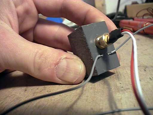
| Back to the diary | As I found out in another longer test, my ultra cheap laser barriers from 7.12. did not work as reliable as I wanted them to be. I mean, they are part of the main safety feature of the whole Gallerydrive, so they should work almost 100% reliable. Even if the principle, how the barriers work is still the same, I have changed the circuit, the black tube and the type of the lasers, that I am using. On the picture below, you can see a part of vinyl with some holes in it. Inside the upper hole, I've put a 5mW class 3a industrial laser module. This is the highest laser class, which you can use without the need of wearing special laser safety glasses. I would have taken stronger lasers as well, just because I would find it cool to use some dangerous techniques for the setup. But I simply can't afford to supply every visitor with those glasses. |
|
|
||
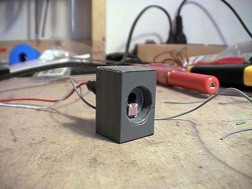
That's the other side of the vinyl piece. Below, you can see the LDR. Above, there's the hole for the laser beam. I have also made some tests with photo diodes instead of LDR's, but the contrast range of the LDR's is much higher than the range of the diodes. So I preferred to use those old school pieces. I guess, that the only advantage of photo diodes or photo transistors compared to light dependant resistors is, that they switch much faster. But I guess, that this are some millisecond dimensions, which really don't matter in my case. |
||
|
||
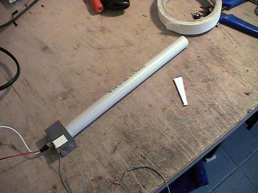
Onto the vinyl piece, I plugged a 20cm long vinyl tube (diameter: 16mm) which I have from the hardware store. This is usually used to cover electric installations. Inside that tube, I have adhered black velour d-c-fix in order to avoid reflections. Don't ask me, how I got the adhesive foil into that tube. I can only tell you, that I've found a very tricky way to do this really quick. |
||
|
||
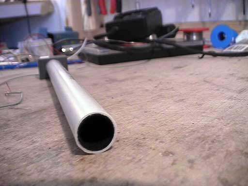
Here, you have a better view on the velour foil. |
||
|
||
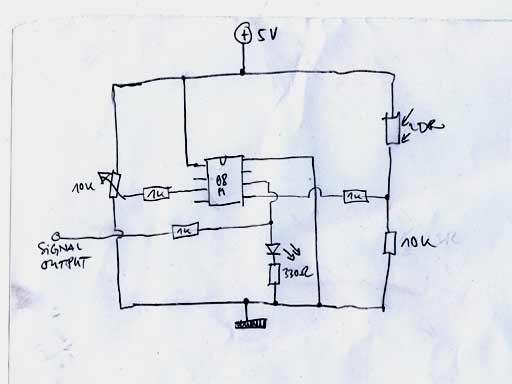
Let's have a quick look on the schematics: On the right side, you can see the detector circuit with the voltage divider. The voltage, which comes from the sensor goes via a 1K safety resistor into pin 5 of a Picaxe 08M microcontroller. This is one of the controller's ADC's. On the left side, the voltage output of a trimmer, which I've used as voltage divider, also goes into one of the 08M's ADC's. I am only using this controller as comparator with hysteresis. Obviously, I could also have taken a far cheaper comparator IC, but I had some of those controllers still at home, so I used them. The digital output switches a LED and goes also through another 1K safety resistor to the signal line of the XLR-plug. The main advantage of this circuit, compared to the older circuit, is the comparator. Together with the trimmer, the laser barrier can now be adjusted and it always delivers an accurate digital signal (while the first version only generated an analogue signal between 0V and something around 3V). |
||
|
||
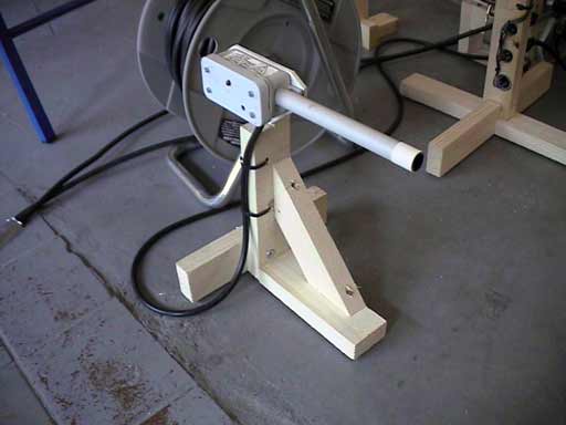
This is the finished laser. I've also built new stands. They are more stabile and reliable than the old version. The disadvantage of the new pieces is, that I don't get them so small for transport. |
||
|
||
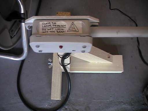
Another closer look on the device. Here, you can see my self drawn laser warning stickers. |
||
|
||
Please note, that the content on this webpage is licensed under a Creative Commons Attribution 2.0 License. Please respect the copyright of other webpages' content, which are linked from this webpage. |
||